$7.58
Add to Cart
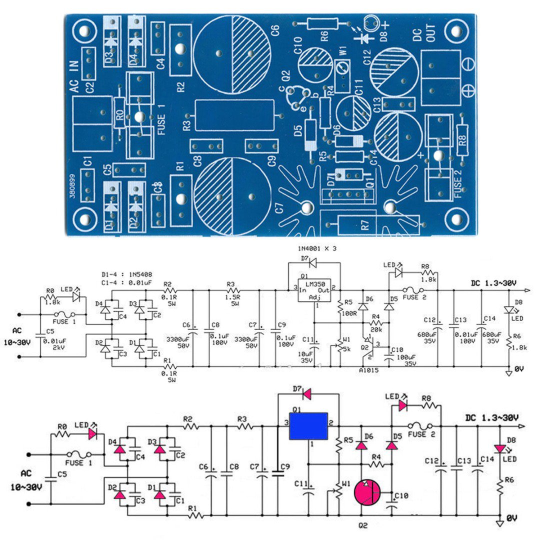
Low Noise Distortion Power Supply PCB LM317 LT1083 LM1085 LM350 Supply Bare Kit
Only 1 available
Details
Shipping: Australia: free (more destinations)
Condition: Brand new
*The store has not been updated recently. You may want to contact the merchant to confirm the availability of the product.


Low Noise Soft Start Linear Regulated Power Supply PCB LM317 LT1083 LM350 125mm Three modes of operation:
1) a simple 2 or 3 π type RC or LC filter.
2) using LM317 / LM350, three-terminal LT1083 / 84/85 and other adjustable regulator blocks.
3) using the LM317 / LM350, LT1083 / 84/85 made constant current power supply circuit.
PCB Size: 12.5x6.7cm
Fixing hole spacing: 11.4x5.4cm
Thickness: 1.6mm, FR4 material, blue solder. Ultra-low noise power supply board member selection:
C1 ~ C4: 22n / 100V, use MKT, pressure or 100V 63V MKP film capacitors, the capacity range of 22 ~ 47nF can be.
C5: 0.01μF / 1KV, ceramic capacitor.
C6, C7: 10000μF35V electrolytic capacitors, the main filter capacitor voltage above 35V, electrolytic diameter of 25mm or less.
C8, C9: 0.22μF100V, 0.47μF100V MKT or MKP film capacitors.
C10: 100μF35V electrolytic capacitors, is part of the soft-start circuit charging capacitor, to increase the capacity of the power soft-start time can be extended.
C11: 10μF35V electrolytic capacitors, after sampling in order to reduce the ripple voltage across the resistor W and set bypass capacitors, plus 15dB ripple rejection effect can be improved.
C12, C14: 100μF35V electrolytic capacitor, the capacity should not be too big, too much effect circuit transient indicators.
C13: 0.1μF100V, MKT or MKP film capacitors.
R1, R2: 0.1Ω5W, current limiting resistor in the range: 0.05 ~ 0.15Ω.
R3: 0.1Ω5W, metal oxide film resistors or white cement resistance, used and C6, C7 constitute RC filter circuit, in the range: 0.01Ω ~ 10Ω5W.
R4: 47K, 1 / 2W metal film resistors, three-terminal adjustable soft-start circuit regulator blocks, increasing the resistance can extend the power soft-start time, is generally preferable 10K ~ 100K.
R5: 200Ω1 / 2W metal film resistors, LM317 minimum load current of not less than 5mA, to ensure the provision of not less than 5mA of load current, max R5 is 1.25V / 5mA = 250 Europe, actual production in Europe of 100 to 240 Room selection.
W1: 5K, 3296 Series multi-turn potentiometer, and R5 constitute the three-terminal adjustable voltage regulator power supply circuit. Using more than 3296 turn potentiometer.
R6: 1K, 1 / 2W metal film resistors, the output of the power indicator LED current limiting resistor.
R7: 1Ω ~ 5Ω, power 3 ~ 5W, metal oxide film resistors, using an IC chip without installation. IC chip is not installed, install the resistor constitutes two RC filter circuit.
R0, R8: 1.8K, 1 / 2W metal film resistors, fuse disconnect is indicated by a red 3mm LED current limiting resistor.
D1 ~ D4: a rectifier diode, which can use ordinary 1N4004,1N5404,10A10, FR307 this diode can also be used TO220 package fast recovery rectifier diodes, such as HFA25PB60 like.
D5 ~ D7: 1N4007, mainly on the three-terminal regulator block provides protection.
D8: 3mm or 5mm emitting LED, the color is not limited, to the power supply output voltage indication.
Q1: LM317, other common LM350, LT1083 / 84/85 series three-terminal adjustable voltage regulator can be used.
Q2: 2SA1015, Vceo = -50V, Ic = 0.15A, β> 40, may also be other similar small power PNP transistor substitution, pinout PCB design is an equilateral triangle, so that better compatibility, install other models Note transistor distinguish pins.
FUSE 1: 5 × 20mm, 2A ~ 10A,
FUSE 2: 5 × 20mm, 2A ~ 5A,
Blown fuse indicating use 3mm red light tube, PCB board not marked, when welding must be installed from the back (below the two fuses), please note the polarity during installation.
Package Included: 1 x Low Distortion Power Supply Bare Board (other parts not included)
You may also be interested in:
-
$13.98

-
$11.18

-
$25.17

-
$13.98

-
$13.98

-
$11.18

-
$26.57

-
$0.94

-
$20.97

-
$80.09


 CN, Hong Kong