
$125.07
Add to Cart
2phase NEMA42 NEMA52 hybrid stepper motor driver DSP AC150V-230V 5.9A MC2280H
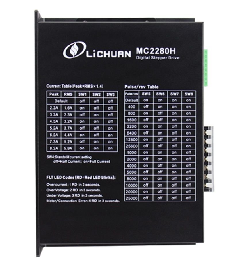


Product Name: two-phase digital stepper driver MC2280HMC2280H adopts advanced servo control principle technology, has the motor parameter self-adapting function, guarantees the best performance of the motor, and is suitable for the 86-130mm two phase hybrid stepping motor. This technology can greatly reduce the noise and vibration of the motor when it is running, and make the noise and stability of the stepping motor approach the level of the servo motor. Compared with most of the market segments of the same type of drive products, stepper motors and drives of thermal decline of 15-30% function description Function Operation instructions Operating current setting The output current of the driver is set by the three dial switches of SW1-SW3, and the output current has 8 levels. For specific output current settings, refer to the drive panel instructions. Automatic half current function Set the auto semi current function of the drive through the SW4. The OFF indicates that the quiescent current is set at half of the dynamic current, and the ON represents the same static current as the dynamic current. For general use, the SW4 shall be set to OFF to reduce heating and improve reliability of the motor and actuator. After the pulse string stops, about 0.4seconds or so, the current automatically reduces by 50% (actual value 65%), the calorific value theoretically reduces 35%. Microstep subdivide setting By the SW5-SW8 four dial switch set microstep subdivide, the total of 15 stalls microstep. When the user sets the subdivision, the drive should be stopped. The micro set, please check the drive panel. Indicator light The drive has red and green lights. The green light is the power indicator lamp. When the drive is powered on, the green light is always on; the red light is the fault indicating lamp, and when the overvoltage and overcurrent faults occur, the trouble lamp is always on. After the fault is clear, the red light goes out. When the drive fails, only the power on and re enable to clear the fault. Signal interface PUL+ and PUL- are the positive and negative ends of the control pulse signals; the DIR+ and DIR- are the positive and negative ends of the directional signal; ENA+ and ENA- are the positive and negative ends of the enabling signals. Motor Interface The A+ and A- are connected with the positive and negative ends of the A phase winding of the stepping motor; B+ and B- are connected with the positive and negative ends of the B phase winding of the stepping motor. When the A and B two phase windings are switched, the motor direction is reversed. Power interface The operating voltage range is recommended as 80-220VAC. Installation instructions Drive dimensions are: 187×137×81mm. It can be installed horizontally or vertically (vertical installation is recommended). When installed, it should be attached to the metal cabinet to facilitate heat dissipation. Application:Suitable for all kinds of motion control automation equipment and instruments, such as electronic processing and testing, semiconductor packaging, laser cutting and welding, laser printing, packaging machinery, engraving machine, marking machine, cutting machine, apparel plotter, CNC machine tools, automatic assembly equipment etc.. It is the first choice for users with low noise, high speed performance and competitive cost performance.
You may also be interested in:
-
$150.45
-
$150.45
-
$150.45

-
$150.45
-
$121.79
-
$816.80

-
$121.79

-
$121.79

-
$300.92

-
$100.30


 CN, Guangdong
